Out Of This World Tips About How To Find Current In Parallel Circuit

Decoding Parallel Circuits
Ever stared at a circuit diagram filled with parallel lines and wondered how electricity manages to navigate that maze? You're not alone! Figuring out the current in a parallel circuit can seem intimidating, but trust me, it's more like understanding a well-organized traffic system than deciphering ancient hieroglyphs. This guide will break down the process into easy-to-digest steps. So, buckle up, grab your (virtual) multimeter, and let's dive in!
At its heart, understanding parallel circuits is all about recognizing how electricity behaves when it has multiple paths to choose from. Imagine a river splitting into several streams — that's essentially what's happening with current in a parallel setup. Instead of all the current being forced down one single path, it distributes itself among the various branches, making things a bit more interesting (and slightly more challenging to calculate, initially).
The good news? There are some handy rules we can use to make sense of it all. By remembering a few key principles — like voltage being consistent across all branches and current dividing based on resistance — you can unlock the secrets of parallel circuit analysis. No more staring blankly at circuit diagrams!
And don't worry about getting lost in technical jargon. We'll keep things practical and relatable, focusing on the 'why' and 'how' rather than getting bogged down in abstract theories. After all, the goal is to equip you with the knowledge you need to tackle real-world circuit problems with confidence. Let's get started!
1. Understanding the Basics
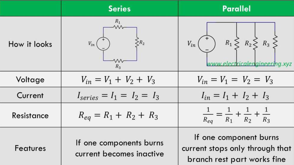
One of the most important things to remember about parallel circuits is that the voltage across each branch is the same. Think of it like this: each branch is directly connected to the power source, so they all experience the same electrical "push" (voltage). This makes our lives easier because we don't have to calculate different voltages for each component.
Why is this constant voltage so important? Well, it gives us a fixed reference point. Since we know the voltage is the same everywhere, we can focus on how the current divides based on the resistance in each branch. It's like knowing the height of a waterfall — that information then helps you understand how the water will flow.
To further illustrate, imagine a simple parallel circuit with two resistors connected to a 12V battery. Both resistors will have 12V across them, regardless of their individual resistances. This voltage value becomes our starting point for calculating the current flowing through each resistor.
This concept is so fundamental that it's worth repeating: in a parallel circuit, the voltage is constant across all branches. Keep this in mind, and you're already halfway to mastering parallel circuit analysis. It's the cornerstone upon which all our calculations will be built.

Circuit Current Equation
Calculating Current in Each Branch
2. Applying Ohm's Law
Here comes our good old friend, Ohm's Law! This is the equation that's going to help us figure out the current flowing through each individual branch of our parallel circuit. Ohm's Law states that Voltage (V) = Current (I) Resistance (R). Rearranging this, we get Current (I) = Voltage (V) / Resistance (R).
Since we already know that the voltage is the same across all branches (thanks to our previous discussion!), we can easily calculate the current in each branch by simply dividing the voltage by the resistance of that branch. For example, if a branch has a resistance of 10 ohms and the voltage is 12V, the current in that branch would be 12V / 10 ohms = 1.2 amps.
Let's say we have a parallel circuit with three branches. Branch 1 has a 5-ohm resistor, Branch 2 has a 10-ohm resistor, and Branch 3 has a 20-ohm resistor. If the voltage source is 20V, then:Current in Branch 1 = 20V / 5 ohms = 4 ampsCurrent in Branch 2 = 20V / 10 ohms = 2 ampsCurrent in Branch 3 = 20V / 20 ohms = 1 amp
See? Not so scary! By applying Ohm's Law to each branch separately, we can determine the current flowing through each resistor. This is the key to understanding how current distributes itself in a parallel circuit. Remember, the lower the resistance, the higher the current, and vice-versa. It's like the electrical current is always looking for the path of least resistance (literally!).
Finding the Total Current: Adding It All Up
3. Summing the Individual Currents: The Grand Finale
Now that we know the current in each branch, finding the total current flowing into the parallel circuit is surprisingly simple: we just add up all the individual branch currents! Think of it as counting the number of cars using each lane on a highway to find the total traffic flow.
In our previous example, we calculated the currents in three branches as 4 amps, 2 amps, and 1 amp, respectively. Therefore, the total current flowing into the parallel circuit is 4 amps + 2 amps + 1 amp = 7 amps. That's it! You've successfully determined the total current in the parallel circuit.
This "adding up" principle is a direct consequence of Kirchhoff's Current Law (KCL), which states that the total current entering a junction (or node) must equal the total current leaving it. In a parallel circuit, the point where the branches split off from the main line is a junction, and the total current entering that junction must equal the sum of the currents flowing through each branch.
So, to reiterate, finding the total current in a parallel circuit involves two easy steps:1. Calculate the current in each branch using Ohm's Law (I = V/R).2. Add up all the individual branch currents to find the total current.With these steps, you can confidently tackle any parallel circuit current calculation!
Calculating Equivalent Resistance: Simplifying the Circuit
4. The Reciprocal Method: Making It Easy
Sometimes, you might want to simplify a parallel circuit by finding the equivalent resistance. This is the single resistance that would have the same effect on the circuit as all the parallel resistors combined. Finding the equivalent resistance can make further circuit analysis much easier, especially when dealing with more complex circuits.
The formula for calculating the equivalent resistance (Req) of resistors in parallel is:1/Req = 1/R1 + 1/R2 + 1/R3 + ... (and so on for all the resistors)
Then, once you've calculated the sum of the reciprocals, you take the reciprocal of the result to find Req. For instance, if you have two resistors in parallel, one with 10 ohms and the other with 20 ohms:1/Req = 1/10 + 1/20 = 3/20Req = 20/3 = 6.67 ohms (approximately)
Therefore, the equivalent resistance of the two parallel resistors is approximately 6.67 ohms. You can now replace the two resistors with a single 6.67-ohm resistor without changing the overall behavior of the circuit. Calculating equivalent resistance is a powerful tool for simplifying complex parallel circuits and making them easier to analyze.
Real-World Applications: Where You'll See Parallel Circuits
5. From Homes to Electronics: Parallel Circuits Everywhere
Parallel circuits aren't just abstract concepts — they're all around us! Understanding how they work can give you a deeper appreciation for the technology that powers our lives. Think about the electrical wiring in your home, for example. Appliances and lights are typically connected in parallel so that each device receives the full voltage from the mains.
Why parallel and not series? Because in a parallel circuit, if one appliance fails or is switched off, the others continue to operate without interruption. Imagine if your entire house went dark every time a light bulb blew! That's the beauty of parallel wiring.
Beyond homes, parallel circuits are found in various electronic devices, such as computers, televisions, and audio equipment. They're also used in power distribution systems to ensure a stable voltage supply to different loads. Even in your car, the headlights, taillights, and other electrical components are wired in parallel for reliability.
So, the next time you switch on a light or plug in an appliance, remember that you're witnessing the practical application of parallel circuit principles. Understanding these principles not only helps you troubleshoot electrical problems but also gives you a glimpse into the ingenious design of the systems we rely on every day. Its not just theory; its real-world electricity in action!
FAQ: Your Parallel Circuit Questions Answered
6. Q: What happens to the total current if I add more branches to a parallel circuit?
A: Adding more branches to a parallel circuit provides more paths for the current to flow, effectively lowering the overall resistance. As the resistance decreases, the total current drawn from the source increases, assuming the voltage remains constant.
7. Q: What if the branches in a parallel circuit have different wire gauges (thicknesses)? Does this affect the current?
A: Yes, the wire gauge affects the resistance of the branch. Thicker wires have lower resistance, allowing more current to flow. Thinner wires have higher resistance, limiting the current. This difference in resistance will influence how the total current is distributed among the branches.
8. Q: Can I use a calculator to help me find the reciprocal of equivalent resistance?
A: Absolutely! Using a calculator to find the reciprocal (1/x button) and to perform the addition is highly recommended, especially when dealing with multiple resistors or resistors with non-integer values. It makes the calculation much faster and less prone to errors.
9. Q: Is it safe to add unlimited branches to a parallel circuit?
A: While theoretically you can* add as many branches as you want, in reality, there are limitations. Each additional branch draws more current, potentially overloading the power source or the wiring. It's crucial to consider the current capacity of the source and the wires to prevent overheating or damage. Always consult electrical codes and safety guidelines before modifying any electrical circuit.

Current Calculation In A Parallel Circuit Mastering Electrical

How To Find The Total Voltage Of A Parallel Circuit Wiring Diagram

