First Class Info About Do Resistors In Series Have The Same Voltage

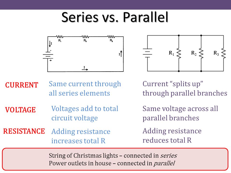
Chapter 25 Electric Circuits Ppt Video Online Download
Unraveling the Mystery
Ever wondered about what happens to voltage when you string resistors together like beads on a necklace in a series circuit? It's a fundamental concept in electronics, and understanding it can unlock a whole new level of understanding when dealing with circuits. Let's dive in and clarify this important topic. The answer, in short, is no, resistors in series do not have the same voltage across them. That's the main idea to keep in mind. But let's understand the why behind it!
1. Voltage Isn't Shared Equally
Imagine a water pipe with different constrictions along its length. The water pressure will drop more significantly where the pipe is narrower. Resistors act like those constrictions to the flow of electrical current. In a series circuit, the current has only one path to flow. But the resistors, if they have different resistance values, offer different amounts of "opposition" to that flow. Ohm's Law (V=IR) tells us voltage is directly proportional to resistance when current is constant. This is very important to remember.
Therefore, the resistor with the higher resistance will "hog" a larger portion of the total voltage. Think of it like dividing a pizza where one person gets a bigger slice because they are much more hungry. The pizza is analogous to the total voltage supply, and the slice size is the voltage drop accross individual resistor.
To bring this home, consider a series circuit with a 9V battery and two resistors: a 1k resistor and a 2k resistor. The 2k resistor, having twice the resistance of the 1k resistor, will experience twice the voltage drop. The distribution of voltage is proportional to resistance in this particular circuit.
So, when you see resistors lined up in series, don't assume they're all experiencing the same voltage. It's all about their individual resistance values.
2. Current
While voltage isn't shared equally, there's something that is: the current. In a series circuit, the current is the same through every component. It's like a single lane road where all cars must move at the same rate or things just won't flow right.
This uniform current is key to understanding why the voltage drops are different. Since V=IR, and 'I' is the same for all resistors, the 'V' (voltage drop) is directly dependent on 'R' (resistance). A larger resistance will always lead to a larger voltage drop, given a constant current.
Think of it as a team of oxen pulling a cart. The force (current) applied by the oxen is the same on all parts of the cart. However, if one section of the cart has more friction (resistance), it will require more effort to pull that section forward (voltage drop).
So while resistors in series don't get the same voltage, they share the same current, and that's a fundamental concept to keep in mind when analyzing series circuits.
3. Calculating Voltage Drops
Let's get our hands dirty with a practical calculation to solidify this understanding. Suppose you have a series circuit powered by a 12V source, with two resistors: R1 = 300 and R2 = 500. How do you determine the voltage across each resistor?
First, calculate the total resistance: R_total = R1 + R2 = 300 + 500 = 800. Next, use Ohm's Law to find the current: I = V / R_total = 12V / 800 = 0.015A (or 15mA).
Now, apply Ohm's Law again to find the voltage drop across each resistor: V1 = I R1 = 0.015A 300 = 4.5V. V2 = I R2 = 0.015A 500 = 7.5V. Notice that V1 + V2 = 4.5V + 7.5V = 12V, which equals the source voltage. This confirms our calculations are accurate and is a great sanity check.
As you can see, the 500 resistor "drops" more voltage (7.5V) than the 300 resistor (4.5V), reinforcing the principle that larger resistance equals larger voltage drop in a series circuit. Remember: always double check your work to ensure you have properly calcuated!
4. Power Dissipation and Heat
Voltage drop isn't just a theoretical concept — it has real-world consequences. As resistors impede the flow of current, they dissipate power in the form of heat. The power dissipated by a resistor is calculated as P = IV, where P is power, I is current, and V is voltage.
Since resistors in series experience different voltage drops (assuming they have different resistance values) they dissipate different amounts of power. The resistor with the larger voltage drop will dissipate more power and get hotter. This is something to consider when selecting resistors for a circuit, especially if the circuit handles significant amounts of power. You don't want to melt your components!
Therefore, if you have two resistors in series and one is getting noticeably hotter than the other, that's a good indication that it has a higher resistance and, consequently, a larger voltage drop and power dissipation.
This heat generation can be a problem, so make sure that you properly space your components, use heat sinks, or chose higher wattage resistors to accommodate the generated heat.
5. Why This Matters
Understanding that resistors in series don't have the same voltage is crucial for both circuit design and troubleshooting. In circuit design, you can strategically use series resistors to create specific voltage dividers. This is a common technique for creating reference voltages or biasing transistors.
If you know the total voltage and resistance values, you can calculate the voltage at any point in the series circuit. This allows you to design circuits that provide the correct voltages to different components.
When troubleshooting, if a circuit isn't behaving as expected, measuring the voltage across each resistor can provide valuable clues. If one resistor has a significantly higher voltage drop than anticipated, it might indicate that its resistance value has changed (perhaps due to damage or overheating) or that another component in the circuit is malfunctioning.
So, remembering that voltage distribution is not uniform across series resistors is a valuable tool for diagnosing circuit problems and getting your project back on track. Use it!

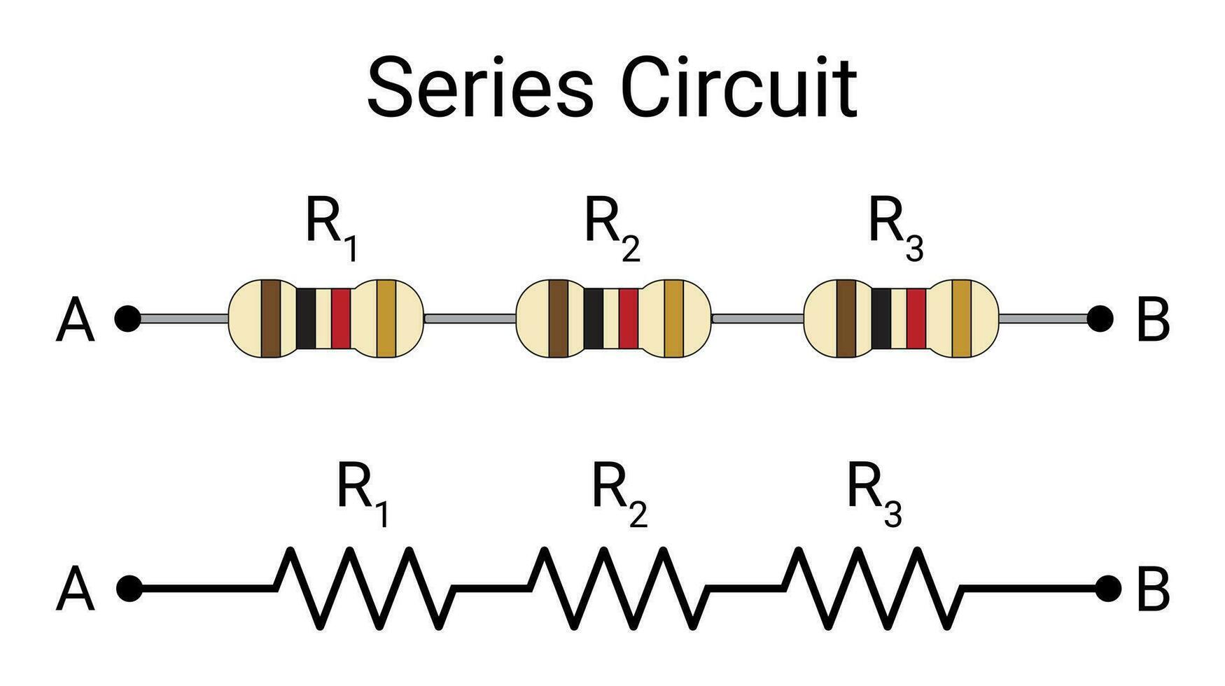
Series Connection Of Resistors 26149296 Vector Art At Vecteezy
FAQs About Resistors in Series and Voltage
6. Q
A: The current! In a series circuit, the current is the same through every component. It's like a single-lane road where all the cars are flowing at the same rate.
7. Q
A: Absolutely! This is the basis of a voltage divider. By carefully selecting the resistance values, you can create a circuit that provides the exact voltage you need at a particular point.
8. Q
A: If a resistor burns out, it essentially becomes an open circuit, breaking the path for current flow. This will cause the entire circuit to stop functioning, as no current can flow through any of the components.

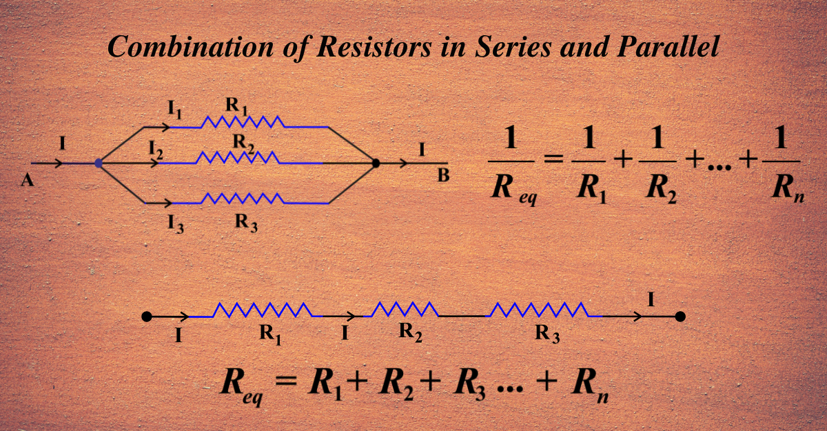
Combination Of Resistors In Series And Parallel Unifyphysics


